

YCSH heating approval passwords
- E24*10R06/02*5936*00
- E49*122R00/06*1050*00
- CE EMC DL-240923008EC
- CE LVD DL-240923017SC
YCSH Stationary Heating Installation Instructions, management and maintenance
Intended use of the heater
The heater is designed to provide heating and maintain a comfortable temperature in the following vehicles and spaces:
- Vehicles: Automobiles; vans; caravans and motorhomes.
- closed spaces: Cabins; garages; storage rooms and other similar environments.
Operating characteristics:
- Operates independently of the vehicle engine, using diesel fuel as a source of energy.
- Requires an electrical connection 12 V capable of supplying an instantaneous consumption of at least 10 A.
- Includes automatic temperature regulation using a sensor integrated into the control screen.
Use: This equipment ensures efficient and autonomous heating for a wide variety of applications..
Rules for mounting in the vehicle
- Protection against heat and spills: Protect nearby parts and prevent possible spills from damaging other components.
- Distance and ventilation: Maintain adequate distance and ensure sufficient ventilation in the compartment.
- Protective materials: use refractory materials/heat shields if necessary.
- Equipment identification: after installation, affix a copy of the manufacturer's sticker in a visible and accessible place on the vehicle.
Rules for mounting inside the vehicle
- The use of disconnectable connections in the exhaust gas and fuel lines is not permitted..
- The exhaust and intake pipes must be fixed with the supplied clamps and exit to the outside.
- The installation surface must be completely flat (use mounting plate if not).
- On wooden surfaces: trim around the exhaust pipe leaving 2–3 cm, or cut out the perimeter to rest on the vehicle's sheet metal.
fuel supply
- Through “T” connection or sprat installed in the vehicle tank.
- In the portable version, the tank integrated inside the heater can be used.
Important: The tank supplied with non-portable models does not meet essential regulations for use in vehicles (not accepted in ITV). Connect to vehicle tank with kit accessories.
- It will not be accepted in the ITV in Spain.
- The heater must be connected to the vehicle's tank using the accessories included in the installation kit.
For the use of the T piece supplied with the equipment, it can only be used in vehicles in which There is NO pre-pump in the tank. (Otherwise diesel will come out of the heater exhaust/intake when starting the engine..
Depending on the type of vehicle, year, etc. It can be mounted on the OUT or RETURN, In some cases it will be necessary to use a non-return valve to avoid depriming the vehicle's fuel line..
The best way to do this is by installing the spud supplied with the equipment.
Some warehouses already come with a housing or recess in the tank for installation, Some vehicles even come with pre-installation for independent heating..
The fuel line should be as short as possible, and try as far as possible to never exceed the maximum distance of 5m.
It is recommended to install the pump near the fuel tank between 0 y 1m, or as far as the pump cable reaches and that the longest section is always between the pump and the heating (max 4m).
exhaust gas system
⚠ Important warning:
The equipment is designed and adjusted to work with the original exhaust pipe supplied from the factory. It is not recommended to modify its length.
If it is essential to add an extension, this should not exceed 30 additional cm, The same diameter and characteristics of the original tube must be maintained.. An incorrect modification will affect the performance of the equipment, It will generate carbon buildup and cause erratic operation..
- The outlet must be installed completely avoiding the possibility of gases entering the interior.
-
Keep the exhaust outlet away from any opening or air intake in the passenger compartment..
Combustion air intake
⚠ Important warning:
The combustion intake pipe is calculated and adjusted for this equipment. It is strictly prohibited to lengthen it or modify its diameter or characteristics.. Shortening is only allowed when necessary for installation.
Any unauthorized modification may cause incomplete combustion due to lack of air., malfunctions, Carbon buildup and voiding warranty.
- The air for the combustion chamber must not be extracted from the interior of the vehicle.
- Intake must be installed/protected so that it cannot become clogged.
Hot air intake
- Can be taken from inside (recirculation) or from outside (in a place with clean air, not contaminated by leaks).
- If taken from outside: Protect the duct with a grill and locate the intake, avoiding contamination by harmful gases..
Hot air outlet
Ducts must be installed securely. It is essential to ensure that the exit cannot be blocked.
In case of using a boiler with hot air inlet in conjunction with the heating, It is recommended to mount a Y to divide the flow of hot air so that it does not all pass through the boiler.
Installation
Permitted mounting positions
- Recommended: normal position.
- Leaning: up to 30°, with the lower end towards the hot air outlet.
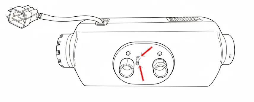
- Turned: 90° towards only one side; diesel inlet and spark plug always up.
Outdoor mounting
- Splash protection: sheltered from water, snow or dirt.
- Orientation: horizontal with downward exhaust and inclination up to 30°; if rotated 90°, spark plug and diesel inlet always up as in the image above.
- Gas evacuation: The exhaust pipe must be oriented so that the gases cannot re-enter the vehicle or affect sensitive components.. A slight downward slope or the inclusion of a 4mm drain hole at the lowest point is recommended to allow condensate to escape.
- Distances: Always maintain adequate distance between the exhaust system and heat-sensitive components, Take care that it cannot burn electrical cables., brake hoses, fuel lines and other plastic components.
- Robust fixation: The heater must be firmly attached by its original anchors to avoid damage from vibrations and deformations..
- Supports and waterproof boxes Use specific mounting brackets or waterproof boxes for greater protection of the heater against impacts and splashes of water or snow.
Changing the position of the cable harness
If necessary, it is possible to change the harness connection to the opposite side:
- Remove the top cover.
- Remove the cable and slide it under the motor to the opposite end.
- Remove the rubber plug from the opposite end before attaching the cable.
- The useful length of the cable will be considerably reduced.
- Put the rubber plug on the original end and mount the top cover.
Mounting and fixing the heater
To ensure safe and stable heater installation, follow these instructions:
Drilling:
Use the mounting plate/template included in the kit to drill the necessary holes to:
- The escape.
- Air intake for combustion.
- fuel connection.
Using the mounting plate:
It is mandatory to use the mounting plate if the surface where the heater will be installed has ribs., shocks or irregularities.
The plate ensures that the heater rests on a completely flat surface, avoiding deformation and ensuring stable installation.
Fastening and support surface:
-
Under no circumstances place the heater directly on overhangs., objects, cabling, insulators or other components.
-
housing contact (aluminum or plastic) with external elements can cause deformations that block the engine and generate irreversible damage not covered by the warranty..
Sealed:
-
Properly install the rubber seal provided to prevent gases from entering through the holes made.
Minimum separation between walls and furniture
Minimum recommended 5 cm. If it were not possible:
- Aluminum casing: can be attached (it barely takes temperature).
- Plastic casing: mandatory minimum 2 cm (difficult disassembly/maintenance).
Hot air conduction
Install Pipes Safely. If suction duct is not installed, keep grid; if pipes are installed, put equivalent grid 2kw o 5kw according to the case.
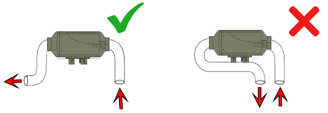
Do not draw the air to be heated right at the hot air outlet, separate them as much as possible.
Avoid very sharp curves until after 10 cm of the outlet, and avoid 90° bends right at the heating outlet, otherwise the unit may give an error due to overheating..
Exhaust pipe in the portable version
The portable heater includes two exhaust sections, each designed for a specific use:
- short section: Should only be used on the outside of the vehicle. It is designed to be mounted when the heating is placed on the floor, allowing it to be folded and direct the exhaust gases to the side.
- long section: Designed for fixed installations, It has a double layer that makes it more robust and guarantees a better seal. A silencer can be cut and inserted in the desired position. In this case, the short section can be placed after the silencer, but never before.

Install the combustion intake so that it does not draw in exhaust gases (as far away as possible; if possible, opposite side).
Protect intake so that air/water/mud/snow does not enter. Exhaust as straight as possible and with downward inclination; if there is a “belly”, make drainage drilling.
Muffler preferably as in the picture; but, horizontal with slight downward inclination. The final section after the silencer must point to the ground.

Ideal inclination between 15º and 35º (can go vertical). The electrical connector side is the outlet and should be higher.
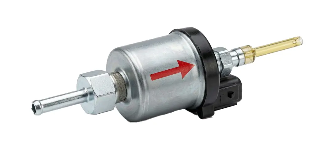
Use: “Silent” pump supplied. If it sounds loud, check position and possible air. to purge, can be placed vertically and run until the air is eliminated.
Control panel installation
The panel includes a temperature probe: Placing it incorrectly can distort the reading..
- Do not install in front of a draft or on a metal surface.
- Excessive handling heats the panel and temporarily distorts the reading.
- If cut/spliced to lengthen: do not reverse cables (damages screen, no warranty).
- It is not recommended to extend more than 5/6 m.
Battery Power System Recommendations
cable 2,5 mm² suitable up to 2 m from battery. For longer distance or non-optimal lead/AGM/GEL batteries:
- Cut near the main connector.
- Splice larger section cable (4 mm² o 6 mm² depending on distance).
Caution: voltage less than 11,8 V can cause failures (Bad/discharged battery or insufficient cable voltage drop), poor combustion and soot.
Testing the heater after installation
- Check that the propeller rotates freely (if it is blocked, can damage engine; does not cover warranty).
- Check battery voltage ≥ 11,8 V (visible on screen).
- Check configuration: size (2 kW o 5 kW) and type of pump (22 ml).
- Bleed fuel until it reaches the heater; avoid over purging (on laptop max 20 s).
Functional tests on first start
If you purged excessively, there will be white smoke 5–10 min. Put maximum power (power mode 10). After ~15 min there should be no smoke.
Then minimum power (1), wait for stabilization and observe escape: should not emit black smoke.
If it emits black smoke in either test, contact technical service: garantias@ycsh.es
Warning: If it has been purged excessively and a lot of white smoke comes out, DO NOT turn off the heating; leave it on until it disappears completely.
Heating start phases
- The fan starts to spin slightly.
- The glow plug lights up (40–60 s).
- The pump runs intermittently.
- After 3–4 minutes, an increase in temperature begins to be noticed. (it is not instantaneous).
Use: In the first few hours it may emit an unpleasant odor. (combustion/burned plastic); It is normal and will decrease with use. Can be accelerated at maximum power for several hours with the vehicle ventilated.
Portable version / independent deposit: At the end of the season it must be empty and clean. If the diesel breaks down (more yellow/sediment color), Drain and clean with gasoline or kerosene before reuse.
Residual consumption: screen/control unit consume something. If there is no solar panel, It is recommended to disconnect from the battery to avoid discharge.
YCSH heating maintenance
Fixed equipment
To ensure optimal operation, It is advisable to turn on the equipment for approximately 15 minutes each 30-40 days at maximum power. This allows the fuel accumulated in the pump and pipes to be renewed., avoiding its degradation.
Laptop
- Recommended option: Completely empty the fuel tank and turn on the heating until it goes out with the error 8.
- Alternative (if the assembly does not allow total emptying): Fill the tank with small amounts of fuel and consume them in the same proportion. This helps to renew the fuel without leaving accumulations in the tank..
Consequences of not performing maintenance
Over time, diesel tends to degrade due to the presence of biodiesel and humidity, what causes:
✅ A color change to a more intense yellow.
✅ Formation of sticky sediments at the bottom of the tank.
✅ Possible appearance of diesel bacteria.
These residues can adhere to the pump piston, hindering its movement and causing:
❌ Poor performance.
❌ Total pump blockage.
❌ Expensive and complicated repairs. (depending on equipment and assembly)
Carrying out this periodic maintenance is key to prolonging the useful life of the equipment and avoiding breakdowns that will not be covered in the warranty..
Contact & information of interest
For more information or questions: Write to us HERE
Most updated version of the manual and others: https://ycsh.es/descargas/
Activation of the warranty of a YCSH heating
Activation of mandatory warranty for heating in: https://ycsh.es/garantia/
It must be done after assembly and before 365 days from purchase.
The warranty only covers manufacturing defects, no damage resulting from incorrect assembly (carbon or damage).
Important: Activation must be carried out when the assembly has been carried out by an individual or by a workshop that does not belong to our network of workshops.. This verification is necessary to certify that the product has been installed correctly and that it does not pose a risk to human safety..
Visual verification also allows detecting possible installation problems that, if not corrected, could lead to damage due to incorrect assembly.
This activation process is designed to validate the initial installation of the equipment, not to process incidents when the product has already been in operation for a while and has errors.