

YCSH-värmares homologeringskoder
- E24*10R06/02*5936*00
- E49*122R00/06*1050*00
- CE EMC DL-240923008EC
- CE LVD DL-240923017SC
YCSH parkeringsvärmare · Installation, drift- och underhållsinstruktioner
Avsedd användning av värmaren
Värmaren är utformad för att ge uppvärmning och hålla en behaglig temperatur i följande fordon och utrymmen:
- Fordon: Bilar; skåpbilar; husvagnar och husbilar.
- Slutna utrymmen: Stugor; garage; förråd och andra liknande miljöer.
Driftsegenskaper:
- Fungerar oberoende av fordonets motor, använder diesel som energikälla.
- Kräver en 12 V elektrisk anslutning som kan leverera en momentan förbrukning på minst 10 A.
- Inkluderar automatisk temperaturreglering via en sensor integrerad i kontrolldisplayen.
Notera: Denna enhet säkerställer effektiv och autonom uppvärmning för en mängd olika applikationer.
Regler för installation i fordonet
- Skydd mot värme och spill: skydda närliggande delar och förhindra eventuellt spill från att skada andra komponenter.
- Avstånd och ventilation: håll tillräckligt avstånd och säkerställ tillräcklig ventilation i facket.
- Skyddsmaterial: använd eldfasta/termiska skyddsmaterial vid behov.
- Identifiering av utrustning: efter installationen, fäst en kopia av tillverkarens etikett på en synlig och tillgänglig plats i fordonet.
Regler för installation inuti fordonet
- Användning av löstagbara anslutningar i avgas- och bränsleledningar är inte tillåten.
- Avgas- och insugsrör ska fästas med de medföljande klämmorna och dras utåt.
- Installationsytan måste vara helt plan (använd monteringsplatta om den inte är det).
- På träytor: skär runt avgasröret och lämna 2–3 cm, eller skär av omkretsen så att den vilar på fordonets metallplåt.
Bränsletillförsel
- Via en "T"-anslutning eller pickuprör installerat i fordonets tank.
- I den bärbara versionen, tanken integrerad i värmaren kan användas.
Viktig: Tanken som levereras med icke-portabla modeller överensstämmer inte med väsentliga bestämmelser för användning i fordon (inte accepteras vid fordonsbesiktning). Anslut till fordonets tank med hjälp av satsens tillbehör.
- Det kommer inte att accepteras vid fordonsbesiktning i Spanien.
- Värmaren måste anslutas till fordonets tank med tillbehören som ingår i installationssatsen.
För användning av det medföljande T-stycket, den får endast användas i fordon där INGEN förpump finns i tanken. (Annars kommer diesel ut genom värmarens avgaser/intag när motorn startas.)
Beroende på typ av fordon, år, etc., den kan installeras på SUPPLY eller RETURN-linjen. I vissa fall kommer det att vara nödvändigt att använda en backventil för att förhindra förlust av fyllning i fordonets bränsleledning.
Det bästa sättet att göra detta är genom att installera pickupröret som medföljer enheten.
Vissa tankar har redan en avsedd plats eller urtagning för installation, och vissa fordon kommer till och med med en förinstallation för en extra värmare.
Bränsleledningen ska vara så kort som möjligt, och försök att inte överskrida det maximala avståndet för 5 m.
Det rekommenderas att installera pumpen nära bränsletanken mellan 0 och 1 m, eller så långt som pumpkabeln tillåter, se till att den längsta sektionen alltid är mellan pumpen och värmaren (max 4 m).
Avgassystem
⚠ Viktig varning:
Enheten är designad och kalibrerad för att fungera med originalavgasröret som levereras från fabriken. Det rekommenderas inte att ändra dess längd.
Om det är nödvändigt att lägga till en förlängning, den får inte överstiga 30 cm ytterligare, bibehålla samma diameter och egenskaper som originalröret. Felaktig modifiering kommer att påverka prestandan, orsaka kolansamling och leda till oregelbunden drift.
- Utloppet måste installeras så att ingen möjlighet att gaser kommer in i det inre undviks.
-
Håll avgasutloppet borta från eventuella öppningar eller luftintag i kabinen.
Förbränningsluftintag
⚠ Viktig varning:
Förbränningsluftens intagsrör beräknas och kalibreras för denna enhet. Det är strängt förbjudet att förlänga den eller ändra dess diameter eller egenskaper. Den får endast förkortas om det behövs för installationen.
Alla otillåtna ändringar kan orsaka ofullständig förbränning på grund av brist på luft, felfunktion, kolansamling och ogiltigförklara garantin.
- Luft till förbränningskammaren får inte tas inifrån fordonet.
- Intaget måste installeras/skyddas så att det inte kan blockeras.
Varmluftsintag
- Den kan tas inifrån (återcirkulation) eller utanför (på en plats med ren luft, inte förorenad av avgaser).
- Om det tas utifrån: skydda kanalen med ett galler och placera intaget för att undvika kontaminering från skadliga gaser.
Varmluftsutlopp
Kanalerna måste installeras säkert. Det är viktigt att se till att uttaget inte kan blockeras.
Om man använder en panna med varmluftsintag tillsammans med värmaren, det rekommenderas att installera en Y att dela upp varmluftsflödet så att allt inte passerar genom pannan.
Installation
Tillåtna monteringslägen
- Rekommenderad: normal position.
- Lutande: upp till 30°, med den nedre änden mot varmluftsutloppet.
- Roterat: 90° åt ena sidan; bränsleinlopp och glödstift alltid uppåt.
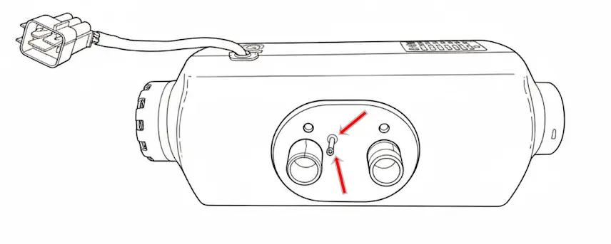
Utomhusinstallation
- Skydd mot stänk: skyddad från vatten, snö eller smuts.
- Orientering: horisontellt med utblås nedåt och lutning upp till 30°; om den vrids 90°, glödstift och bränsleinlopp alltid uppe som visas ovan.
- Gasevakuering: Avgasröret måste vara orienterat så att gaser inte kan komma in i fordonet igen eller påverka känsliga komponenter. En lätt lutning nedåt eller en 4 mm dräneringshål på den lägsta punkten rekommenderas för att kondensat ska kunna rinna ut
- Avstånd: Håll alltid tillräckligt avstånd mellan avgassystemet och värmekänsliga komponenter. Se till att den inte kan bränna elektriska kablar, bromsslangar, bränsleledningar och andra plastkomponenter.
- Säker fastsättning: Värmaren måste fästas ordentligt med sina originalfästen för att förhindra skador från vibrationer och deformation.
- Fästen och förseglade lådor Använd specifika monteringsfästen eller förseglade lådor för bättre skydd mot stötar och stänk av vatten eller snö.
Ändra ledningsnätets position
Om så behövs, seleanslutningen kan flyttas till motsatt sida:
- Ta bort topplocket.
- Ta bort kabeln och skjut in den under motorn till motsatt ände.
- Ta bort gummipluggen från den motsatta änden innan du placerar kabeln.
- Den användbara kabellängden kommer att minska avsevärt.
- Placera gummipluggen på originaländen och sätt tillbaka topplocket.
Montering och fixering av värmaren
För att säkerställa en säker och stabil installation av värmaren, följ dessa riktlinjer:
Borrning:
Använd monteringsplattan/mall som ingår i satsen för att göra de nödvändiga hålen för:
- Avgaserna.
- Förbränningsluftintag.
- Bränsleanslutning.
Användning av monteringsplattan:
Det är obligatoriskt att använda monteringsplattan om ytan där värmaren ska installeras har ribbor, stötar eller oegentligheter.
Plattan säkerställer att värmaren vilar på en helt plan yta, förhindrar deformation och säkerställer en stabil installation.
Fixerings- och stödyta:
-
Värmaren får under inga omständigheter placeras direkt på stötar, föremål, ledningar, isolering eller andra komponenter.
-
Kontakt av höljet (aluminium eller plast) med externa element kan orsaka deformation som blockerar motorn och genererar irreversibla skador som inte täcks av garantin.
Tätning:
-
Correctly install the rubber seal provided to prevent gases from entering through the holes made.
Minimum clearance between walls and furniture
Recommended minimum 5 cm. If not possible:
- Aluminum casing: can be flush (barely heats up).
- Plastic casing: mandatory minimum 2 cm (makes disassembly/maintenance more difficult).
Hot air ducting
Install ducts securely. If no intake duct is installed, keep the grille; if ducts are installed, use an equivalent grille 2kw or 5kw depending on the case.
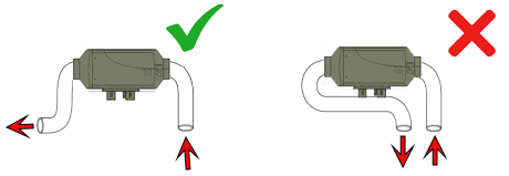
Do not take intake air right next to the hot air outlet; keep them as far apart as possible.
Avoid very sharp bends within the first 10 cm of the outlet, and avoid 90° elbows right at the heater outlet as this may cause overheating errors.
Exhaust pipe in the portable version
The portable heater includes two exhaust sections, each designed for a specific use:
- Short section: Must be used only outside the vehicle. Designed for use when the heater is placed on the ground, allowing it to be bent and direct exhaust gases to the side.
- Long section: Designed for fixed installations, with a double layer for greater robustness and better sealing. It can be cut and a silencer inserted at the desired position. In this case, the short section can be placed after the silencer, but never before.

Install the combustion intake so it does not draw in exhaust gases (as far away as possible; preferably opposite side).
Protect intake to prevent air/water/mud/snow from entering. Exhaust should be as straight as possible with downward inclination; if there is a “belly”, make a drainage hole.
Silencer preferably as shown; otherwise horizontal with slight downward slope. The final section after the silencer must point towards the ground.

Ideal inclination between 15º and 35º (can be vertical). The side with the electrical connector is the outlet and must be higher.
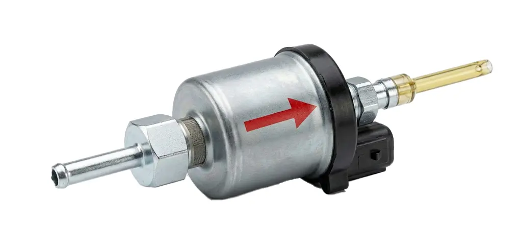
Notera: A “silent” pump is supplied. If it is loud, check position and possible air. To purge, it can be placed vertically and run until air is removed.
Control panel installation
The panel includes a temperature sensor: incorrect placement may distort readings.
- Do not install in front of airflow or on metal surfaces.
- Excessive handling heats the panel and temporarily distorts readings.
- If cutting/splicing to extend: do not reverse wires (damages display, no warranty).
- Extending more than 5/6 m is not recommended.
Battery power supply system recommendations
2.5 mm² cable is suitable up to 2 m from the battery. For longer distances or non-optimal lead/AGM/GEL batteries:
- Cut near the main connector.
- Splice in a larger section cable (4 mm² or 6 mm² depending on distance).
Caution: voltage below 11.8 V may cause failures (bad/discharged battery or voltage drop due to insufficient cable), poor combustion and soot.
Heater test after installation
- Check that the fan spins freely (if blocked, it may damage the motor; not covered by warranty).
- Check battery voltage ≥ 11.8 V (visible on screen).
- Verify configuration: size (2 kW or 5 kW) and pump type (22 ml).
- Prime fuel until it reaches the heater; avoid excessive priming (bärbar max 20 s).
Operation tests on first start
If over-primed, there will be white smoke for 5–10 min. Set maximum power (power mode 10). After ~15 min it should not emit smoke.
Then minimum power (1), wait for stabilization and observe exhaust: it should not emit black smoke.
If it emits black smoke in either test, contact technical service: garantias@ycsh.es
Warning: If over-primed and heavy white smoke appears, DO NOT turn off the heater; leave it running until it disappears completely.
Heater startup phases
- The fan starts spinning slightly.
- The glow plug turns on (40–60 s).
- The pump operates intermittently.
- After 3–4 min, temperature increase becomes noticeable (not instant).
Notera: During the first hours it may emit an unpleasant smell (combustion/burning plastic); this is normal and will decrease with use. It can be accelerated by running at maximum power for several hours with the vehicle ventilated.
Portable version / independent tank: at the end of the season it must be empty and clean. If diesel degrades (more yellow color/sediments), drain and clean with gasoline or kerosene before reuse.
Residual consumption: display/control unit consumes some power. If there is no solar panel, it is recommended to disconnect from the battery to prevent discharge.
YCSH heater maintenance
Fixed unit
To ensure optimal operation, it is recommended to run the unit for approximately 15 minuter every 30–40 days at maximum power. This helps renew the fuel accumulated in the pump and lines, preventing degradation.
Portable unit
- Recommended option: Completely empty the fuel tank and run the heater until it stops with fel 8.
- Alternativ (if installation does not allow full draining): Refill the tank with small amounts of fuel and consume them proportionally. This helps renew the fuel without leaving buildup in the tank.
Consequences of not performing maintenance
Over time, diesel tends to degrade due to the presence of biodiesel and moisture, causing:
✅ A color change to a more intense yellow.
✅ Formation of sticky sediments at the bottom of the tank.
✅ Possible appearance of diesel bacteria.
These residues can adhere to the pump piston, hindering its movement and causing:
❌ Poor operation.
❌ Total pump blockage.
❌ Costly and complex repairs. (depending on the unit and installation)
Performing this periodic maintenance is key to extending the unit’s lifespan and avoiding failures not covered by warranty.
Kontakta & useful information
For more information or questions: Write to us HERE
Most up-to-date version of the manual and others: https://ycsh.es/descargas/
Activation of YCSH heater warranty
Mandatory warranty activation for heaters at: https://ycsh.es/garantia/
Must be completed after installation and within 365 days from purchase.
The warranty only covers manufacturing defects, not damage resulting from incorrect installation (carbon buildup or failures).
Viktig: Activation must be carried out when installation has been performed by a private individual or by a workshop outside our network. This verification is necessary to certify that the product has been installed correctly and does not pose a safety risk.
The visual verification also allows detection of possible installation issues which, if not corrected, could lead to damage due to incorrect installation.
This activation process is designed to validate the initial installation of the unit, not to process incidents when the product has already been in operation for some time and presents faults.