

Codes d'homologation des appareils de chauffage YCSH
- E24*10R06/02*5936*00
- E49*122R00/06*1050*00
- CE CEM DL-240923008EC
- CE LVD DL-240923017SC
Chauffage de stationnement YCSH · Installation, instructions d'utilisation et d'entretien
Utilisation prévue du radiateur
Le chauffage est conçu pour fournir du chauffage et maintenir une température confortable dans les véhicules et espaces suivants:
- Véhicules: Voitures; fourgonnettes; caravanes et camping-cars.
- Espaces clos: Cabines; garages; salles de stockage et autres environnements similaires.
Caractéristiques de fonctionnement:
- Fonctionne indépendamment du moteur du véhicule, utiliser du carburant diesel comme source d'énergie.
- Nécessite un 12 V raccordement électrique capable de fournir une consommation instantanée d'au moins 10 UN.
- Comprend une régulation automatique de la température via un capteur intégré à l'écran de contrôle.
Note: Cette unité assure un chauffage efficace et autonome pour une grande variété d'applications.
Règles d'installation dans le véhicule
- Protection against heat and spills: protect nearby parts and prevent possible spills from damaging other components.
- Distance and ventilation: maintain adequate distance and ensure sufficient ventilation in the compartment.
- Protective materials: use refractory/thermal protection materials if necessary.
- Equipment identification: after installation, attach a copy of the manufacturer’s label in a visible and accessible place in the vehicle.
Rules for installation inside the vehicle
- The use of detachable connections in exhaust gas and fuel lines is not permitted.
- Exhaust and intake pipes must be fixed with the supplied clamps and routed outside.
- The installation surface must be completely flat (use mounting plate if it is not).
- On wooden surfaces: cut around the exhaust pipe leaving 2–3 cm, ou découper le périmètre pour qu'il repose sur la tôle du véhicule.
Alimentation en carburant
- Via un raccord en « T » ou un tube de prélèvement installé dans le réservoir du véhicule.
- Dans la version portable, le réservoir intégré à l'intérieur du radiateur peut être utilisé.
Important: Le réservoir fourni avec les modèles non portables n'est pas conforme aux réglementations essentielles à l'utilisation dans les véhicules (non accepté lors de l'inspection des véhicules). Se connecte au réservoir du véhicule à l'aide du kit d'accessoires.
- Il ne sera pas accepté lors du contrôle technique des véhicules en Espagne.
- Le chauffage doit être connecté au réservoir du véhicule à l'aide des accessoires inclus dans le kit d'installation..
Pour l'utilisation de la pièce en T fournie, il ne peut être utilisé que dans des véhicules où AUCUNE pré-pompe n'existe dans le réservoir. (Sinon, du diesel sortira par l'échappement/l'admission du chauffage lors du démarrage du moteur.)
Depending on the type of vehicle, year, etc., it may be installed on the SUPPLY or RETURN line. In some cases it will be necessary to use a non-return valve to prevent losing prime in the vehicle fuel line.
The best way to do this is by installing the pickup tube supplied with the unit.
Some tanks already have a designated location or recess for installation, and some vehicles even come with a pre-installation for an auxiliary heater.
The fuel line should be as short as possible, and try not to exceed the maximum distance of 5 m.
It is recommended to install the pump near the fuel tank between 0 et 1 m, or as far as the pump cable allows, ensuring the longest section is always between the pump and the heater (maximum 4 m).
Exhaust gas system
⚠ Important warning:
The unit is designed and calibrated to operate with the original exhaust pipe supplied from the factory. Modifying its length is not recommended.
If it is essential to add an extension, it must not exceed 30 cm additional, maintaining the same diameter and characteristics as the original pipe. Incorrect modification will affect performance, cause carbon buildup and lead to erratic operation.
- The outlet must be installed avoiding any possibility of gases entering the interior.
-
Keep the exhaust outlet away from any openings or air intakes of the cabin.
Combustion air intake
⚠ Important warning:
The combustion air intake pipe is calculated and calibrated for this unit. It is strictly forbidden to lengthen it or modify its diameter or characteristics. It may only be shortened if necessary for installation.
Toute modification non autorisée peut provoquer une combustion incomplète en raison du manque d'air, mauvais fonctionnement, accumulation de carbone et annuler la garantie.
- L'air de la chambre de combustion ne doit pas provenir de l'intérieur du véhicule..
- L'admission doit être installée/protégée afin qu'elle ne puisse pas être bloquée.
Prise d'air chaud
- On peut le prendre de l'intérieur (recirculation) ou à l'extérieur (dans un endroit avec de l'air pur, non contaminé par les gaz d'échappement).
- Si pris de l’extérieur: protéger le conduit avec une grille et placer l'admission en évitant la contamination par des gaz nocifs.
Sortie d'air chaud
Les conduits doivent être installés solidement. Il est essentiel de s'assurer que la prise ne peut pas être bloquée.
Si vous utilisez une chaudière avec entrée d'air chaud avec le chauffage, il est recommandé d'installer un Oui diviser le flux d'air chaud pour qu'il ne passe pas tout dans la chaudière.
Installation
Allowed mounting positions
- Recommended: normal position.
- Inclined: up to 30°, with the lower end towards the hot air outlet.
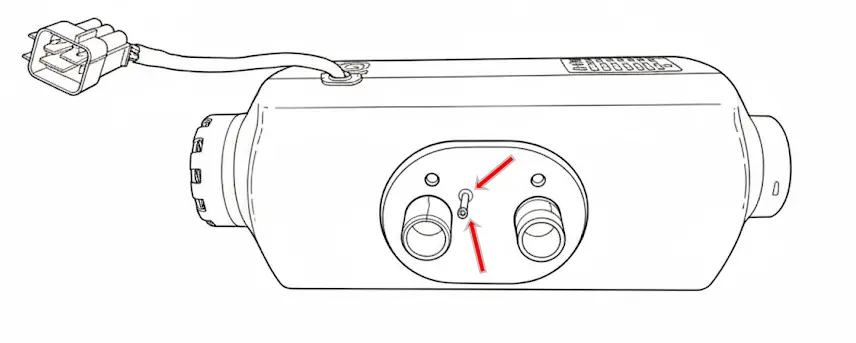
- Rotated: 90° to one side; fuel inlet and glow plug always upwards.
Outdoor installation
- Protection against splashes: sheltered from water, snow or dirt.
- Orientation: horizontal with exhaust facing down and inclination up to 30°; if rotated 90°, glow plug and fuel inlet always up as shown above.
- Gas evacuation: The exhaust pipe must be oriented so gases cannot re-enter the vehicle or affect sensitive components. A slight downward inclination or a 4 mm drainage hole at the lowest point is recommended to allow condensate to escape
- Distances: Always maintain adequate distance between the exhaust system and heat-sensitive components. Ensure it cannot burn electrical cables, brake hoses, fuel lines and other plastic components.
- Secure fastening: The heater must be firmly fixed using its original mounts to prevent damage from vibrations and deformation.
- Brackets and sealed boxes Use specific mounting brackets or sealed boxes for better protection against impacts and splashes of water or snow.
Changing the wiring harness position
If necessary, the harness connection can be moved to the opposite side:
- Remove the top cover.
- Remove the cable and slide it under the motor to the opposite end.
- Remove the rubber plug from the opposite end before placing the cable.
- The usable cable length will be considerably reduced.
- Place the rubber plug on the original end and reinstall the top cover.
Mounting and fixing the heater
To ensure a safe and stable installation of the heater, suivez ces directives:
Forage:
Utilisez la plaque de montage/le gabarit inclus dans le kit pour réaliser les trous nécessaires pour:
- L'échappement.
- Combustion air intake.
- Raccordement carburant.
Utilisation de la plaque de montage:
Il est obligatoire d'utiliser la plaque de montage si la surface sur laquelle le radiateur sera installé présente des nervures, bosses ou irrégularités.
La plaque garantit que le radiateur repose sur une surface complètement plane, empêchant la déformation et assurant une installation stable.
Surface de fixation et d'appui:
-
En aucun cas le radiateur ne doit être placé directement sur des bosses, objets, câblage, isolation ou autres composants.
-
Contact du boîtier (aluminium ou plastique) avec des éléments extérieurs peut provoquer une déformation qui bloque le moteur et génère des dommages irréversibles non couverts par la garantie.
Scellage:
-
Correctly install the rubber seal provided to prevent gases from entering through the holes made.
Minimum clearance between walls and furniture
Recommended minimum 5 cm. If not possible:
- Aluminum casing: can be flush (barely heats up).
- Plastic casing: mandatory minimum 2 cm (makes disassembly/maintenance more difficult).
Hot air ducting
Install ducts securely. If no intake duct is installed, keep the grille; if ducts are installed, use an equivalent grille 2kW or 5kW depending on the case.
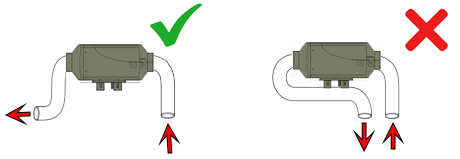
Do not take intake air right next to the hot air outlet; keep them as far apart as possible.
Avoid very sharp bends within the first 10 cm of the outlet, and avoid 90° elbows right at the heater outlet as this may cause overheating errors.
Exhaust pipe in the portable version
The portable heater includes two exhaust sections, each designed for a specific use:
- Short section: Must be used only outside the vehicle. Designed for use when the heater is placed on the ground, allowing it to be bent and direct exhaust gases to the side.
- Long section: Designed for fixed installations, with a double layer for greater robustness and better sealing. It can be cut and a silencer inserted at the desired position. In this case, the short section can be placed after the silencer, but never before.

Install the combustion intake so it does not draw in exhaust gases (as far away as possible; preferably opposite side).
Protect intake to prevent air/water/mud/snow from entering. Exhaust should be as straight as possible with downward inclination; if there is a “belly”, make a drainage hole.
Silencer preferably as shown; otherwise horizontal with slight downward slope. The final section after the silencer must point towards the ground.

Ideal inclination between 15º and 35º (can be vertical). The side with the electrical connector is the outlet and must be higher.
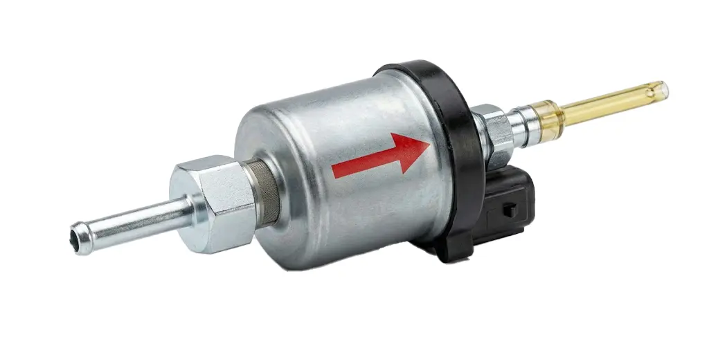
Note: A “silent” pump is supplied. If it is loud, check position and possible air. To purge, it can be placed vertically and run until air is removed.
Control panel installation
The panel includes a temperature sensor: incorrect placement may distort readings.
- Do not install in front of airflow or on metal surfaces.
- Excessive handling heats the panel and temporarily distorts readings.
- If cutting/splicing to extend: do not reverse wires (damages display, no warranty).
- Extending more than 5/6 m is not recommended.
Battery power supply system recommendations
2.5 mm² cable is suitable up to 2 m from the battery. For longer distances or non-optimal lead/AGM/GEL batteries:
- Cut near the main connector.
- Splice in a larger section cable (4 mm² or 6 mm² depending on distance).
Caution: voltage below 11.8 V may cause failures (bad/discharged battery or voltage drop due to insufficient cable), poor combustion and soot.
Heater test after installation
- Check that the fan spins freely (if blocked, it may damage the motor; not covered by warranty).
- Check battery voltage ≥ 11.8 V (visible on screen).
- Verify configuration: size (2 kW or 5 kW) and pump type (22 ml).
- Prime fuel until it reaches the heater; avoid excessive priming (portable maximum 20 s).
Operation tests on first start
If over-primed, there will be white smoke for 5–10 min. Set maximum power (power mode 10). After ~15 min it should not emit smoke.
Then minimum power (1), wait for stabilization and observe exhaust: it should not emit black smoke.
If it emits black smoke in either test, contact technical service: garantias@ycsh.es
Warning: If over-primed and heavy white smoke appears, DO NOT turn off the heater; leave it running until it disappears completely.
Heater startup phases
- The fan starts spinning slightly.
- The glow plug turns on (40–60 s).
- The pump operates intermittently.
- After 3–4 min, temperature increase becomes noticeable (not instant).
Note: During the first hours it may emit an unpleasant smell (combustion/burning plastic); this is normal and will decrease with use. It can be accelerated by running at maximum power for several hours with the vehicle ventilated.
Portable version / independent tank: at the end of the season it must be empty and clean. If diesel degrades (more yellow color/sediments), drain and clean with gasoline or kerosene before reuse.
Residual consumption: display/control unit consumes some power. If there is no solar panel, it is recommended to disconnect from the battery to prevent discharge.
YCSH heater maintenance
Fixed unit
To ensure optimal operation, it is recommended to run the unit for approximately 15 minutes every 30–40 days at maximum power. This helps renew the fuel accumulated in the pump and lines, preventing degradation.
Portable unit
- Recommended option: Completely empty the fuel tank and run the heater until it stops with erreur 8.
- Alternative (if installation does not allow full draining): Refill the tank with small amounts of fuel and consume them proportionally. This helps renew the fuel without leaving buildup in the tank.
Consequences of not performing maintenance
Over time, diesel tends to degrade due to the presence of biodiesel and moisture, causing:
✅ A color change to a more intense yellow.
✅ Formation of sticky sediments at the bottom of the tank.
✅ Possible appearance of diesel bacteria.
These residues can adhere to the pump piston, hindering its movement and causing:
❌ Poor operation.
❌ Total pump blockage.
❌ Costly and complex repairs. (depending on the unit and installation)
Performing this periodic maintenance is key to extending the unit’s lifespan and avoiding failures not covered by warranty.
Contact & useful information
For more information or questions: Write to us HERE
Most up-to-date version of the manual and others: https://ycsh.es/descargas/
Activation of YCSH heater warranty
Mandatory warranty activation for heaters at: https://ycsh.es/garantia/
Must be completed after installation and within 365 days from purchase.
The warranty only covers manufacturing defects, not damage resulting from incorrect installation (carbon buildup or failures).
Important: Activation must be carried out when installation has been performed by a private individual or by a workshop outside our network. This verification is necessary to certify that the product has been installed correctly and does not pose a safety risk.
The visual verification also allows detection of possible installation issues which, if not corrected, could lead to damage due to incorrect installation.
This activation process is designed to validate the initial installation of the unit, not to process incidents when the product has already been in operation for some time and presents faults.