

Códigos de homologação do aquecedor YCSH
- E24*10R06/02*5936*00
- E49*122R00/06*1050*00
- CE EMC DL-240923008EC
- Marcação LVD DL-240923017SC
Aquecedor de estacionamento YCSH · Instalação, instruções de operação e manutenção
Uso pretendido do aquecedor
O aquecedor foi projetado para fornecer aquecimento e manter uma temperatura confortável nos seguintes veículos e espaços:
- Veículos: Carros; vans; caravanas e autocaravanas.
- Espaços fechados: Cabanas; garagens; salas de armazenamento e outros ambientes semelhantes.
Características operacionais:
- Opera independentemente do motor do veículo, usando óleo diesel como fonte de energia.
- Requer um 12 V ligação elétrica capaz de fornecer um consumo instantâneo de pelo menos 10 UM.
- Inclui regulação automática de temperatura através de um sensor integrado no display de controle.
Observação: Esta unidade garante aquecimento eficiente e autônomo para uma ampla variedade de aplicações.
Regras para instalação no veículo
- Proteção contra calor e derramamentos: proteja as peças próximas e evite que possíveis derramamentos danifiquem outros componentes.
- Distância e ventilação: mantenha distância adequada e garanta ventilação suficiente no compartimento.
- Materiais de proteção: use materiais refratários/de proteção térmica, se necessário.
- Identificação do equipamento: após a instalação, anexar uma cópia da etiqueta do fabricante em local visível e acessível no veículo.
Regras para instalação dentro do veículo
- O uso de conexões removíveis em gases de escape e linhas de combustível não é permitido.
- Os tubos de exaustão e admissão devem ser fixados com as braçadeiras fornecidas e encaminhados para fora.
- A superfície de instalação deve ser completamente plana (use a placa de montagem se não estiver).
- Em superfícies de madeira: corte ao redor do tubo de escape deixando 2–3 cm, ou corte o perímetro para apoiar na chapa metálica do veículo.
Fornecimento de combustível
- Através de uma conexão “T” ou tubo captador instalado no tanque do veículo.
- Na versão portátil, o tanque integrado dentro do aquecedor pode ser usado.
Importante: O tanque fornecido com modelos não portáteis não atende às normas essenciais para uso em veículos (não aceito na inspeção veicular). Conecte ao tanque do veículo usando o kit de acessórios.
- Não será aceito na inspeção veicular na Espanha.
- O aquecedor deve ser conectado ao tanque do veículo utilizando os acessórios incluídos no kit de instalação.
Para o uso da peça em T fornecida, só pode ser utilizado em veículos onde NÃO existe pré-bomba no tanque. (Caso contrário, o diesel sairá pela exaustão/admissão do aquecedor ao dar partida no motor.)
Dependendo do tipo de veículo, ano, etc., pode ser instalado na linha FORNECIMENTO ou RETORNO. Em alguns casos será necessário utilizar uma válvula de retenção para evitar a perda de escorva na linha de combustível do veículo.
A melhor maneira de fazer isso é instalando o tubo captador fornecido com a unidade.
Alguns tanques já possuem um local ou recesso designado para instalação, e alguns veículos ainda vêm com pré-instalação de aquecedor auxiliar.
A linha de combustível deve ser a mais curta possível, e tente não exceder a distância máxima de 5 eu.
Recomenda-se instalar a bomba perto do tanque de combustível entre 0 e 1 eu, ou na medida em que o cabo da bomba permitir, garantindo que a seção mais longa esteja sempre entre a bomba e o aquecedor (máx. 4 eu).
Sistema de gases de escape
⚠ Aviso importante:
A unidade foi projetada e calibrada para operar com o tubo de escape original fornecido de fábrica. Modificar seu comprimento não é recomendado.
Se for essencial adicionar uma extensão, não deve exceder 30 cm adicionais, mantendo o mesmo diâmetro e características do tubo original. Modificação incorreta afetará o desempenho, causar acúmulo de carbono e levar a operação errática.
- A saída deve ser instalada evitando qualquer possibilidade de entrada de gases no interior.
-
Mantenha a saída de exaustão longe de quaisquer aberturas ou entradas de ar da cabine.
Entrada de ar de combustão
⚠ Aviso importante:
O tubo de entrada de ar de combustão é calculado e calibrado para esta unidade. É expressamente proibido alongá-lo ou modificar seu diâmetro ou características. Só pode ser encurtado se necessário para instalação.
Any unauthorized modification may cause incomplete combustion due to lack of air, malfunction, carbon buildup and void the warranty.
- Air for the combustion chamber must not be taken from inside the vehicle.
- The intake must be installed/protected so it cannot become blocked.
Hot air intake
- It can be taken from inside (recirculation) or outside (in a place with clean air, not contaminated by exhaust fumes).
- If taken from outside: protect the duct with a grille and place the intake avoiding contamination from harmful gases.
Hot air outlet
The ducts must be installed securely. It is essential to ensure that the outlet cannot become blocked.
If using a boiler with hot air inlet together with the heater, it is recommended to install a S to split the hot air flow so it does not all pass through the boiler.
Installation
Posições de montagem permitidas
- Recomendado: posição normal.
- Inclinado: até 30°, com a extremidade inferior voltada para a saída de ar quente.
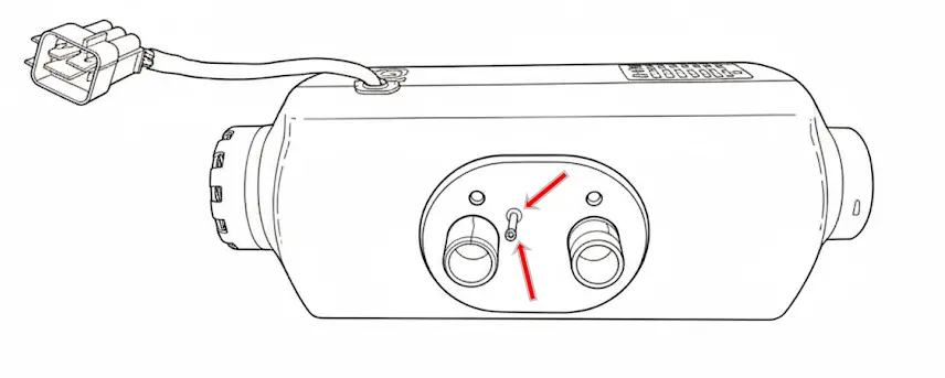
- Girado: 90° para um lado; entrada de combustível e vela de incandescência sempre para cima.
Instalação externa
- Proteção contra respingos: protegido da água, neve ou sujeira.
- Orientação: horizontal com exaustão voltada para baixo e inclinação de até 30°; se girado 90°, vela incandescente e entrada de combustível sempre levantadas conforme mostrado acima.
- Evacuação de gás: O tubo de escape deve ser orientado de forma que os gases não possam entrar novamente no veículo ou afetar componentes sensíveis. Uma ligeira inclinação para baixo ou uma 4 Recomenda-se um orifício de drenagem de mm no ponto mais baixo para permitir que o condensado escape
- Distâncias: Mantenha sempre uma distância adequada entre o sistema de escape e os componentes sensíveis ao calor. Certifique-se de que não pode queimar cabos elétricos, mangueiras de freio, linhas de combustível e outros componentes plásticos.
- Fixação segura: O aquecedor deve ser firmemente fixado usando seus suportes originais para evitar danos causados por vibrações e deformações.
- Suportes e caixas seladas Utilize suportes de montagem específicos ou caixas seladas para melhor proteção contra impactos e respingos de água ou neve.
Alterando a posição do chicote elétrico
Se necessário, a conexão do chicote pode ser movida para o lado oposto:
- Remova a tampa superior.
- Remova o cabo e deslize-o sob o motor até a extremidade oposta.
- Remova o tampão de borracha da extremidade oposta antes de colocar o cabo.
- O comprimento útil do cabo será consideravelmente reduzido.
- Coloque o tampão de borracha na extremidade original e reinstale a tampa superior.
Montagem e fixação do aquecedor
To ensure a safe and stable installation of the heater, follow these guidelines:
Drilling:
Use the mounting plate/template included in the kit to make the necessary holes for:
- The exhaust.
- Entrada de ar de combustão.
- Fuel connection.
Use of the mounting plate:
It is mandatory to use the mounting plate if the surface where the heater will be installed has ribs, bumps or irregularities.
The plate ensures the heater rests on a completely flat surface, preventing deformation and ensuring a stable installation.
Fixing and support surface:
-
Under no circumstances should the heater be placed directly on bumps, objects, wiring, insulation or other components.
-
Contact of the casing (aluminum or plastic) with external elements may cause deformation that blocks the motor and generates irreversible damage not covered by warranty.
Sealing:
-
Correctly install the rubber seal provided to prevent gases from entering through the holes made.
Minimum clearance between walls and furniture
Recommended minimum 5 cm. If not possible:
- Aluminum casing: can be flush (barely heats up).
- Plastic casing: mandatory minimum 2 cm (makes disassembly/maintenance more difficult).
Hot air ducting
Install ducts securely. If no intake duct is installed, keep the grille; if ducts are installed, use an equivalent grille 2kw or 5kw depending on the case.
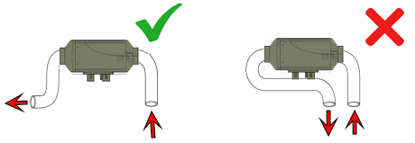
Do not take intake air right next to the hot air outlet; keep them as far apart as possible.
Avoid very sharp bends within the first 10 cm of the outlet, and avoid 90° elbows right at the heater outlet as this may cause overheating errors.
Exhaust pipe in the portable version
The portable heater includes two exhaust sections, each designed for a specific use:
- Short section: Must be used only outside the vehicle. Designed for use when the heater is placed on the ground, allowing it to be bent and direct exhaust gases to the side.
- Long section: Designed for fixed installations, with a double layer for greater robustness and better sealing. It can be cut and a silencer inserted at the desired position. In this case, the short section can be placed after the silencer, but never before.

Install the combustion intake so it does not draw in exhaust gases (as far away as possible; preferably opposite side).
Protect intake to prevent air/water/mud/snow from entering. Exhaust should be as straight as possible with downward inclination; if there is a “belly”, make a drainage hole.
Silencer preferably as shown; caso contrário, horizontal com ligeira inclinação descendente. A seção final após o silenciador deve apontar para o solo.

Inclinação ideal entre 15º e 35º (pode ser vertical). O lado com o conector elétrico é a tomada e deve ser mais alto.
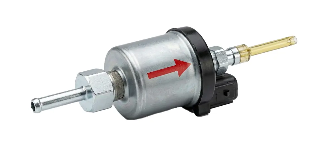
Observação: Uma bomba “silenciosa” é fornecida. Se estiver alto, verifique a posição e possível ar. Para limpar, pode ser colocado verticalmente e funcionar até que o ar seja removido.
Instalação do painel de controle
O painel inclui um sensor de temperatura: posicionamento incorreto pode distorcer as leituras.
- Não instale na frente do fluxo de ar ou em superfícies metálicas.
- O manuseio excessivo aquece o painel e distorce temporariamente as leituras.
- Se cortar/emendar para estender: não inverta os fios (exibição de danos, sem garantia).
- Estendendo mais do que 5/6 m não é recomendado.
Battery power supply system recommendations
2.5 mm² cable is suitable up to 2 m from the battery. For longer distances or non-optimal lead/AGM/GEL batteries:
- Cut near the main connector.
- Splice in a larger section cable (4 mm² or 6 mm² depending on distance).
Caution: voltage below 11.8 V may cause failures (bad/discharged battery or voltage drop due to insufficient cable), poor combustion and soot.
Heater test after installation
- Check that the fan spins freely (if blocked, it may damage the motor; not covered by warranty).
- Check battery voltage ≥ 11.8 V (visible on screen).
- Verify configuration: size (2 kW or 5 kW) and pump type (22 ml).
- Prime fuel until it reaches the heater; avoid excessive priming (portable max 20 é).
Operation tests on first start
If over-primed, there will be white smoke for 5–10 min. Set maximum power (power mode 10). After ~15 min it should not emit smoke.
Then minimum power (1), wait for stabilization and observe exhaust: it should not emit black smoke.
If it emits black smoke in either test, contact technical service: garantias@ycsh.es
Warning: If over-primed and heavy white smoke appears, DO NOT turn off the heater; leave it running until it disappears completely.
Heater startup phases
- The fan starts spinning slightly.
- The glow plug turns on (40–60s).
- The pump operates intermittently.
- After 3–4 min, temperature increase becomes noticeable (not instant).
Observação: During the first hours it may emit an unpleasant smell (combustion/burning plastic); this is normal and will decrease with use. It can be accelerated by running at maximum power for several hours with the vehicle ventilated.
Portable version / independent tank: at the end of the season it must be empty and clean. If diesel degrades (more yellow color/sediments), drain and clean with gasoline or kerosene before reuse.
Residual consumption: display/control unit consumes some power. If there is no solar panel, it is recommended to disconnect from the battery to prevent discharge.
YCSH heater maintenance
Fixed unit
To ensure optimal operation, it is recommended to run the unit for approximately 15 minutes every 30–40 days at maximum power. This helps renew the fuel accumulated in the pump and lines, preventing degradation.
Portable unit
- Recommended option: Completely empty the fuel tank and run the heater until it stops with erro 8.
- Alternative (if installation does not allow full draining): Refill the tank with small amounts of fuel and consume them proportionally. This helps renew the fuel without leaving buildup in the tank.
Consequences of not performing maintenance
Over time, diesel tends to degrade due to the presence of biodiesel and moisture, causing:
✅ A color change to a more intense yellow.
✅ Formation of sticky sediments at the bottom of the tank.
✅ Possible appearance of diesel bacteria.
These residues can adhere to the pump piston, hindering its movement and causing:
❌ Poor operation.
❌ Total pump blockage.
❌ Costly and complex repairs. (depending on the unit and installation)
Performing this periodic maintenance is key to extending the unit’s lifespan and avoiding failures not covered by warranty.
Contact & useful information
For more information or questions: Write to us HERE
Most up-to-date version of the manual and others: https://ycsh.es/descargas/
Activation of YCSH heater warranty
Mandatory warranty activation for heaters at: https://ycsh.es/garantia/
Must be completed after installation and within 365 days from purchase.
The warranty only covers manufacturing defects, not damage resulting from incorrect installation (carbon buildup or failures).
Importante: Activation must be carried out when installation has been performed by a private individual or by a workshop outside our network. This verification is necessary to certify that the product has been installed correctly and does not pose a safety risk.
The visual verification also allows detection of possible installation issues which, if not corrected, could lead to damage due to incorrect installation.
This activation process is designed to validate the initial installation of the unit, not to process incidents when the product has already been in operation for some time and presents faults.